Color gamut
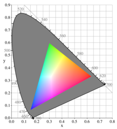
The grayed-out horseshoe shape is the entire range of possible chromaticities, displayed in the CIE 1931 chromaticity diagram format (see below). The colored triangle is the gamut available to the sRGB color space typically used in computer monitors; it does not cover the entire space. The corners of the triangle are the primary colors for this gamut; in the case of a CRT, they depend on the colors of the phosphors of the monitor. At each point, the brightest possible RGB color of that chromaticity is shown, resulting in the bright Mach band stripes corresponding to the edges of the RGB color cube.
In color reproduction and colorimetry, a gamut, or color gamut /ˈɡæmət/, is a convex set containing the colors that can be accurately represented, i.e. reproduced by an output device (e.g. printer or display) or measured by an input device (e.g. camera or visual system). Devices with a larger gamut can represent more colors. Similarly, gamut may also refer to the colors within a defined color space, which is not linked to a specific device. A trichromatic gamut is often visualized as a color triangle. A less common usage defines gamut as the subset of colors contained within an image, scene or video.
Introduction
The term gamut was adopted from the field of music, where the medieval Latin expression "gamma ut" meant the lowest tone of the G scale and, in time, came to imply the entire range of musical notes of which musical melodies are composed. Shakespeare's use of the term in The Taming of the Shrew is sometimes attributed to the author / musician Thomas Morley.[1] In the 1850s, the term was applied to a range of colors or hue, for example by Thomas de Quincey, who wrote "Porphyry, I have heard, runs through as large a gamut of hues as marble."[2]
The gamut of a device or process is that portion of the color space that can be represented, or reproduced. Generally, the color gamut is specified in the hue–saturation plane, as a system can usually produce colors over a wide intensity range within its color gamut. Device gamuts must use real primaries (those that can be represented by a physical spectral power distribution) and therefore are always incomplete (smaller than the human visible gamut). No gamut defined by a finite number of primaries can represent the entire human visible gamut. Three primaries are necessary for representing an approximation of the human visible gamut. More primaries can be used to increase the size of the gamut. For example, while painting with red, yellow and blue pigments is sufficient for modeling color vision, adding further pigments (e.g. orange or green) can increase the size of the gamut, allowing the reproduction of more saturated colors.
While processing a digital image, the most convenient color model used is the RGB model. Printing the image requires transforming the image from the original RGB color model to the printer's CMYK color model. During this process, the colors from the RGB model which are out of gamut must be somehow converted to approximate values within the CMYK model. Simply trimming only the colors which are out of gamut to the closest colors in the destination space would burn the image. There are several algorithms approximating this transformation, but none of them can be truly perfect, since those colors are simply out of the target device's capabilities. This is why identifying the colors in an image that are out of gamut in the target color space as soon as possible during processing is critical for the quality of the final product. It is also important to remember that there are colors inside the CMYK gamut that are outside the most commonly used RGB color spaces, such as sRGB and Adobe RGB.
Color management
Color management is the process of ensuring consistent and accurate colors across devices with different gamuts. Color management handles the transformations between color gamuts and canonical color spaces to ensure that colors are represented equally on different devices. A device's gamut is defined by a color profile, usually the ICC profile, which relates the gamut to a standardized color space and allows for calibration of the device. Transforming from one gamut to a smaller gamut loses information as out-of-gamut colors are projected on to the smaller gamut and transforming back to the larger gamut does not regain this lost information.
Colorimetry
Colorimetry is the measurement of color, generally in a way that mimics human color perception.[3] Input devices such as digital cameras or scanners are made to mimic trichromatic human color perception and are based on three sensors elements with different spectral sensitivities, ideally aligned approximately with the spectral sensitivities of human photopsins. In this sense, they have a similar gamut to the human visual system. However, most of these devices violate the Luther condition and are not intended to be truly colorimetric, with the exception of tristimulus colorimeters. Higher-dimension input devices, such as multispectral imagers, hyperspectral imagers or spectrometers, capture color at a much larger gamut, dimensionally, than the human visible gamut. To be perceived by humans, the images must first be down-dimensionalized and treated with false color.
Visible gamut
The extent of color that can be detected by the average human, approximated by the standard observer, is the humanly visible gamut. The visible gamut is usually visualized in the CIE 1931 chromaticity diagram, where the spectral locus (curved edge) represents the monochromatic (single-wavelength) or spectral colors. As the device you are using to view the diagram has a smaller gamut than the visible gamut, the colors that are out-of-gamut are reproduced as colors inside the display's gamut. Device gamuts are generally depicted in reference to the visible gamut. The standard observer represents a typical human, but colorblindness leads to a reduced visible gamut.
Color reproduction
Visualization of gamuts
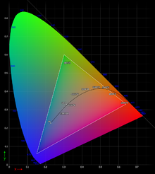 |
Gamuts are commonly represented as areas within the CIE 1931 chromaticity diagram. This ignores the intensity/brightness dimension of the gamut, which is not depicted. Gamuts defined by three primaries are visualized as color triangles. |
The sRGB gamut projected into the CIExyY color space. x and y are the horizontal axes and represent chromaticity. Y is the vertical axis and represents luminance. |
Gamuts may also be represented in 3D space as a color solid, which includes a visualization of the dynamic range of the device. |
sRGB gamut in CIE 1931 XYZ color space Optimal color solid in CIE 1931 XYZ color space, with D65 white point |
The pictures show the gamuts of the sRGB color space (left), which is approximately the one that most computer monitors and TVs have; and the theoretical gamut of surfaces (optimal color solid, or Rösch-MacAdam color solid) (under D65 illumination) (right).
The left diagram shows that the shape of the RGB gamut is a triangle between red, green, and blue at lower luminosities; a triangle between cyan, magenta, and yellow at higher luminosities, and a single white point at maximum luminosity. The exact positions of the apexes depends on the emission spectra of the phosphors in the display, and on the ratio between the maximum luminosities of the three phosphors (i.e., the color balance or white point). |
Limitations of color representation
Surfaces (optimal colors)
Optimal colors are the most chromatic colors that surfaces can have*. The color solid bounded by the set of all optimal colors is called the optimal color solid or Rösch–MacAdam color solid.[4] For now, we are unable to produce objects with such colors, at least not without recurring to more complex physical phenomena.
*(with classical reflection. Phenomena like fluorescence or structural color may produce objects whose color lies outside the optimal color solid)
The reflectance spectrum of a color is the amount of light of each wavelength that it reflects, in proportion to a given maximum, which has the value of 1 (100%). If the reflectance spectrum of a color is 0 (0%) or 1 (100%) across the entire visible spectrum, and it has no more than two transitions between 0 and 1, or 1 and 0, then it is an optimal color. With the current state of technology, we are unable to produce any material or pigment with these properties.[5]
Thus four types of "optimal color" spectra are possible:
- The transition goes from zero at both ends of the spectrum to one in the middle, as shown in the image at right.
- It goes from one at the ends to zero in the middle.
- It goes from 1 at the start of the visible spectrum to 0 in some point in the middle until its end.
- It goes from 0 at the start of the visible spectrum to 1 at some point in the middle until its end.
The first type produces colors that are similar to the spectral colors and follow roughly the horseshoe-shaped portion of the CIE xy chromaticity diagram (the spectral locus), but are, in surfaces, more chromatic, although less spectrally pure. The second type produces colors that are similar to (but, in surfaces, more chromatic and less spectrally pure than) the colors on the straight line in the CIE xy chromaticity diagram (the line of purples), leading to magenta or purple-like colors.

In optimal color solids, the colors of the visible spectrum are theoretically black, because their reflectance spectrum is 1 (100%) in only one wavelength, and 0 in all of the other infinite visible wavelengths that there are, meaning that they have a lightness of 0 with respect to white, and will also have 0 chroma, but, of course, 100% of spectral purity. In short: In optimal color solids, spectral colors are equivalent to black (0 lightness, 0 chroma), but have full spectral purity (they are located in the horseshoe-shaped spectral locus of the chromaticiy diagram).[6]
In linear color spaces that contain all colors visible by humans, such as LMS or CIE 1931 XYZ, the set of half-lines that start at the origin (black, (0, 0, 0)) and pass through all the points that represent the colors of the visible spectrum, and the portion of a plane that passes through the violet half-line and the red half-line (both ends of the visible spectrum), generate the "spectrum cone". The black point (coordinates (0, 0, 0)) of the optimal color solid (and only the black point) is tangent to the "spectrum cone", and the white point ((1, 1, 1)) (only the white point) is tangent to the "inverted spectrum cone", with the "inverted spectrum cone" being symmetrical to the "spectrum cone" with respect to the middle gray point ((0.5, 0.5, 0.5)). This means that, in linear color spaces, the optimal color solid is centrally symmetric.[6]
In most color spaces, the surface of the optimal color solid is smooth, except for two points (black and white); and two sharp edges: the "warm" edge, which goes from black, to red, to orange, to yellow, to white; and the "cold" edge, which goes from black, to blue, to cyan, to white. This is due to the following: If the portion of the reflectance spectrum of a color is spectral red (which is located at one end of the spectrum), it will be seen as black. If the size of the portion of total or reflectance is increased, now covering from the red end of the spectrum to the yellow wavelengths, it will be seen as red. If the portion is expanded even more, covering the green wavelengths, it will be seen as orange or yellow. If it is expanded even more, it will cover more wavelengths than the yellow semichrome does, approaching white, until it is reached when the full spectrum is reflected. The described process is called "cumulation". Cumulation can be started at either end of the visible spectrum (we just described cumulation starting from the red end of the spectrum, generating the "warm" sharp edge), cumulation starting at the violet end of the spectrum will generate the "cold" sharp edge.[6]
Maximum chroma colors, semichromes, or full colors
Each hue has a maximum chroma point, semichrome, or full color; objects cannot have a color of that hue with a higher chroma. They are the most chromatic, vibrant colors that objects can have. They were called semichromes or full colors by the German chemist and philosopher Wilhelm Ostwald in the early 20th century.[6][7]
If B is the complementary wavelength of wavelength A, then the straight line that connects A and B passes through the achromatic axis in a linear color space, such as LMS or CIE 1931 XYZ. If the reflectance spectrum of a color is 1 (100%) for all the wavelengths between A and B, and 0 for all the wavelengths of the other half of the color space, then that color is a maximum chroma color, semichrome, or full color (this is the explanation to why they were called semichromes). Thus, maximum chroma colors are a type of optimal color.[6][7]
As explained, full colors are far from being monochromatic. If the spectral purity of a maximum chroma color is increased, its chroma decreases, because it will approach the visible spectrum, ergo, it will approach black.[6]
In perceptually uniform color spaces, the lightness of the full colors varies from around 30% in the violetish blue hues, to around 90% in the yellowish hues. The chroma of each maximum chroma point also varies depending on the hue; in optimal color solids plotted in perceptually uniform color spaces, semichromes like red, green, blue, violet, and magenta have a high chroma, while semichromes like yellow, orange, and cyan have a slightly lower chroma.

In color spheres and the HSL color space, the maximum chroma colors are located around the equator at the periphery of the color sphere. This makes color solids with a spherical shape inherently non-perceptually uniform, since they imply that all full colors have a lightness of 50%, when, as humans perceive them, there are full colors with a lightness from around 30% to around 90%. A perceptually uniform color solid has an irregular shape.[8][9]
History of the idea of the optimal color solid
In the beginning of the 20th century, industrial demands for a controllable way to describe colors and the new possibility to measure light spectra initiated intense research on mathematical descriptions of colors.
The idea of optimal colors was introduced by the Baltic German chemist Wilhelm Ostwald. Erwin Schrödinger showed in his 1919 article Theorie der Pigmente von größter Leuchtkraft (Theory of Pigments with Highest Luminosity)[5] that the most-saturated colors that can be created with a given total reflectivity are generated by surfaces having either zero or full reflectance at any given wavelength, and the reflectivity spectrum must have at most two transitions between zero and full.
Schrödinger's work was further developed by David MacAdam and Siegfried Rösch.[10] MacAdam was the first person to calculate precise coordinates of selected points on the boundary of the optimal color solid in the CIE 1931 color space for lightness levels from Y = 10 to 95 in steps of 10 units. This enabled him to draw the optimal color solid at an acceptable degree of precision. Because of his achievement, the boundary of the optimal color solid is called the MacAdam limit (1935).
On modern computers, it is possible to calculate an optimal color solid with great precision in seconds. Usually, only the MacAdam limits (the optimal colors, the boundary of the Optimal color solid) are computed, because all the other (non-optimal) possible surface colors exist inside the boundary.

Light sources
Light sources used as primaries in an additive color reproduction system need to be bright, so they are generally not close to monochromatic. That is, the color gamut of most variable-color light sources can be understood as a result of difficulties producing pure monochromatic (single wavelength) light. The best technological source of monochromatic light is the laser, which can be rather expensive and impractical for many systems. However, as optoelectronic technology matures, single-longitudinal-mode diode lasers are becoming less expensive, and many applications can already profit from this; such as Raman spectroscopy, holography, biomedical research, fluorescence, reprographics, interferometry, semiconductor inspection, remote detection, optical data storage, image recording, spectral analysis, printing, point-to-point free-space communications, and fiber optic communications.[11][12][13][14]
Systems that use additive color processes usually have a color gamut which is roughly a convex polygon in the hue-chroma plane (not to be confused with the chromaticity diagram). The vertices of the polygon are the most chromatic colors that the system can produce.
Substractive color mixing
In subtractive color systems, the color gamut is more often an irregular, rounded region.
The gamut of a CMYK color space is, ideally, the same as that for an RGB one. In practice, due to the way raster-printed colors interact with each other and the paper and due to their non-ideal absorption spectra, the gamut has rounded corners.
Comparison of various systems

Following is a list of representative color systems more-or-less ordered from large to small color gamut:
- A laser video projector uses three lasers to produce the broadest gamut available in practical display equipment today, derived from the fact that lasers produce truly monochromatic primaries. The systems work either by scanning the entire picture a dot at a time and modulating the laser directly at high frequency, much like the electron beams in a cathode-ray tube (CRT), or by optically spreading and then modulating the laser and scanning a line at a time, the line itself being modulated in much the same way as in a DLP projector. Lasers can also be used as a light source for a DLP projector. More than three lasers can be combined to increase the gamut range, a technique sometimes used in holography.[15]
- Digital Light Processing or DLP technology is a trademarked technology from Texas Instruments. The DLP chip contains a rectangular array of up to 2 million hinge-mounted microscopic mirrors. Each of the micromirrors measures less than one-fifth the width of a human hair. A DLP chip's micromirror tilts either toward the light source in a DLP projection system (ON) or away from it (OFF). This creates a light or dark pixel on the projection surface.[16] Current DLP projectors use a quickly rotating wheel with transparent colored "pie slices" to present each color frame successively. One rotation shows the complete image.
- Photographic film can reproduce a larger color gamut than typical television, computer, or home video systems.[17]
- CRT and similar video displays have a roughly triangular color gamut which covers a significant portion of the visible color space. In CRTs, the limitations are due to the phosphors in the screen which produce red, green, and blue light.
- Liquid crystal display (LCD) screens filter the light emitted by a backlight. The gamut of an LCD screen is therefore limited to the emitted spectrum of the backlight. Typical LCD screens use cold-cathode fluorescent bulbs (CCFLs) for backlights. LCD Screens with certain LED or wide-gamut CCFL backlights yield a more comprehensive gamut than CRTs. However, some LCD technologies vary the color presented by viewing angle. In Plane Switching or Patterned vertical alignment screens have a wider span of colors than Twisted Nematic.
- Television normally uses a CRT, LCD, LED or plasma display, but does not take full advantage of its color display properties, due to the limitations of broadcasting. The common color profile for TV is based on ITU standard Rec. 601. HDTV is less restrictive and uses a slightly improved color profile based on ITU standard Rec. 709. Still somewhat less than, for example, computer displays using the same display technology. This is due to the use of a limited subset of RGB in broadcasting (values from 16-235), versus full RGB in computer displays, where all bits from 0 to 255 are used.
- Paint mixing, both artistic and for commercial applications, achieves a reasonably large color gamut by starting with a larger palette than the red, green, and blue of CRTs or cyan, magenta, and yellow of printing. Paint may reproduce some highly saturated colors that cannot be reproduced well by CRTs (particularly violet), but overall the color gamut is smaller.[citation needed]
- Printing typically uses the CMYK color space (cyan, magenta, yellow, and black). Very few printing processes do not include black; however, those processes (with the exception of dye-sublimation printers) are poor at representing low saturation, low intensity colors. Efforts have been made to expand the gamut of the printing process by adding inks of non-primary colors; these are typically orange and green (see Hexachrome) or light cyan and light magenta (see CcMmYK color model). Spot color inks of a very specific color are also sometimes used.
- A monochrome display's color gamut is a one-dimensional curve in color space.[18]
Wide color gamut
The Ultra HD Forum defines a wide color gamut (WCG) as a color gamut wider than that of BT.709 (Rec. 709).[19] Color spaces with WCGs include:
- Rec. 2020 – ITU-R Recommendation for UHDTV[20]
- Rec. 2100 – ITU-R Recommendation for HDR-TV (same chromaticity of color primaries and white point as Rec. 2020)[21]
- DCI-P3
- Adobe RGB color space
- DxO Wide Gamut
Extended-gamut printing
The print gamut achieved by using cyan, magenta, yellow, and black inks is sometimes a limitation, for example when printing colors of corporate logos. Therefore, some methods of color printing use additional ink colors to achieve a larger gamut. For example, some use green, orange, and violet inks to increase the achievable saturation of hues near those. These method are variously called heptatone color printing, extended gamut printing, and 7-color printing, etc.[22][23]
References
- ^ Long, John H. (1950). "Shakespeare and Thomas Morley". Modern Language Notes. 65 (1): 17–22. doi:10.2307/2909321. JSTOR 2909321.
- ^ de Quincey, Thomas (1854). De Quincey's works. James R. Osgood. p. 36.
gamut-of-hues 0-1856.
- ^ Ohno, Yoshi (16 October 2000). CIE Fundamentals for Color Measurements (PDF). IS&T NIP16 Intl. Conf. on Digital Printing Technologies. pp. 540–45. Archived from the original (PDF) on 15 May 2009. Retrieved 18 June 2009.
- ^ Perales, Esther; Mora Estevan, Teresa; Viqueira Pérez, Valentin; de Fez, Dolores; Gilabert Pérez, Eduardo José; Martínez-Verdú, Francisco M. (2005). "A new algorithm for calculating the MacAdam limits for any luminance factor, hue angle and illuminant". Repositorio Institucional de la Universidad de Alicante.
- ^ a b Schrödinger, Erwin (1919). "Theorie der Pigmente größter Leuchtkraft". Annalen der Physik. 367 (15): 603–622. Bibcode:1920AnP...367..603S. doi:10.1002/andp.19203671504.
- ^ a b c d e f g Koenderink, Jan; van Doorn, Andrea J.; Gegenfurtner, Karl (2021). "RGB Colors and Ecological Optics". Frontiers in Computer Science. 3. doi:10.3389/fcomp.2021.630370.
- ^ a b Liberini, Simone; Rizzi, Alessandro (2023). "Munsell and Ostwald colour spaces: A comparison in the field of hair colouring". Color Research and Application. 48: 6–20. doi:10.1002/col.22818. hdl:2434/940227.
- ^ "The Dimensions of Colour, lightness, value".
- ^ Munsell (1912), p. 239
- ^ Lee, Hsien-Che (2005). "18.7: Theoretical color gamut". Introduction to Color Imaging Science. Cambridge University Press. p. 468. ISBN 1-139-44455-7. Retrieved 22 September 2022.
- ^ "Single Frequency Laser – Single Longitudinal Mode Laser". Retrieved 26 February 2013.
- ^ "JDSU – Diode Laser, 810 or 830 or 852 nm, 50-200 mW, Single-Mode (54xx Series)". Archived from the original on 25 March 2014. Retrieved 26 February 2013.
- ^ "Laserglow Technologies – Handheld Lasers, Alignment Lasers and Lab / OEM Lasers". Archived from the original on 23 January 2013. Retrieved 26 February 2013.
- ^ "Laser Diode Characteristics". Retrieved 26 February 2013.
- ^ Bjelkhagen, Hans I.; Mirlis, Evangelos (2008). "Color holography to produce highly realistic three-dimensional images". Applied Optics. 47 (4): A123-33. Bibcode:2008ApOpt..47A.123B. doi:10.1364/AO.47.00A123. PMID 18239694.
- ^ "DLP Technology". Retrieved 14 February 2010.
- ^ "Film gamut, apples, and oranges". Archived from the original on 17 September 2008. Retrieved 26 April 2007.
- ^ Velho, Luiz; Frery, Alejandro C.; Gomes, Jonas (29 April 2009). Image Processing for Computer Graphics and Vision. Springer Science & Business Media. ISBN 978-1-84800-193-0.
- ^ Ultra HD Forum (19 October 2020). "Ultra HD Forum Guidelines v2.4" (PDF). Archived (PDF) from the original on 20 November 2021. Retrieved 11 February 2021.
- ^ "BT.2020 : Parameter values for ultra-high definition television systems for production and international programme exchange". www.itu.int. Retrieved 11 February 2021.
- ^ "BT.2100 : Image parameter values for high dynamic range television for use in production and international programme exchange". www.itu.int. Retrieved 11 February 2021.
- ^ Ostromoukhov, Victor (1993). "Chromaticity gamut enhancement by heptatone multi-color printing". Device-independent Color Imaging and Imaging Systems Integration. Vol. 1909. SPIE. pp. 139–151). ISBN 0-8194-1142-6. Retrieved 23 June 2021.
- ^ "Print brand colors accurately with a fixed set of inks".
External links
- Using the Chromaticity Diagram for Color Gamut Evaluation by Bruce Lindbloom.
- Color Gamut Mapping book by Jan Morovic.
- Quantifying Color Gamut by William D. Kappele
- Stanford University CS 178 interactive Flash demo explaining color gamut mapping.
- Wide Color Gamut by Ujjwal Bhardwaj.
Color topics | ||||||||||
|---|---|---|---|---|---|---|---|---|---|---|
| Color science |
|  | ||||||||
| Color philosophy |
| |||||||||
| Color terms |
| |||||||||
| Color organizations | ||||||||||
| Names |
| |||||||||
| Related | ||||||||||